Session 3 : Ultrasonic Sensor
- jugaad club

- May 4, 2021
- 8 min read
Updated: Jun 3, 2021

Definition-
An ultrasonic sensor is an electronic device that measures the distance of a target object by emitting ultrasonic sound waves, and converts the reflected sound into an electrical signal. Ultrasonic waves travel faster than the speed of audible sound (i.e. the sound that humans can hear). Ultrasonic sensors have two main components: the transmitter (which emits the sound using piezoelectric crystals) and the receiver (which encounters the sound after it has travelled to and from the target).
In order to calculate the distance between the sensor and the object, the sensor measures the time it takes between the emission of the sound by the transmitter to its contact with the receiver. The formula for this calculation is D = ½ T x C (where D is the distance, T is the time, and C is the speed of sound ).

Use of Ultrasonic Sensor:
Ultrasonic sensors are used primarily as proximity sensors. They can be found in automobile self-parking technology and anti-collision safety systems. Ultrasonic sensors are also used in robotic obstacle detection systems, as well as manufacturing technology. In comparison to infrared (IR) sensors in proximity sensing applications, ultrasonic sensors are not as susceptible to interference of smoke, gas, and other airborne particles (though the physical components are still affected by variables such as heat).
Ultrasonic sensors are also used as level sensors to detect, monitor, and regulate liquid levels in closed containers (such as vats in chemical factories). Most notably, ultrasonic sensor technology has enabled the medical industry to produce images of internal organs, identify tumors, and ensure the health of babies in the womb.
Construction and Working :
• There are two main parts in the ultrasonic sensor viz. transmitter and receiver. • The transmitter part converts electrical energy into sound and transmits it. • The receiver part receives the echo and turn this received sound waves into electrical energy. • This returned echo is measured and used for distance calculation by the ultrasonic sensor. Basically this sensor calculates time interval between signal transmission and reception of echo and determines the distance of the object from the sensor. As this sensor is used for distance measurement it is known as distance sensor. • Piezoelectric crystals are used in the ultrasonic sensor construction due to the fact that these crystals oscillate at higher range of frequencies.
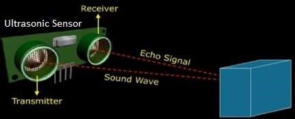
WORKING:
The ultrasonic sensor (or transducer) works on the same principles as a radar system. An ultrasonic sensor can convert electrical energy into acoustic waves and vice versa. The acoustic wave signal is an ultrasonic wave traveling at a frequency above 18kHz. The famous HC SR04 ultrasonic sensor generates ultrasonic waves at 40kHz frequency.
Typically, a microcontroller is used for communication with an ultrasonic sensor. To begin measuring the distance, the microcontroller sends a trigger signal to the ultrasonic sensor. The duty cycle of this trigger signal is 10µS for the HC-SR04 ultrasonic sensor. When triggered, the ultrasonic sensor generates eight acoustic (ultrasonic) wave bursts and initiates a time counter. As soon as the reflected (echo) signal is received, the timer stops. The output of the ultrasonic sensor is a high pulse with the same duration as the time difference between transmitted ultrasonic bursts and the received echo signal.
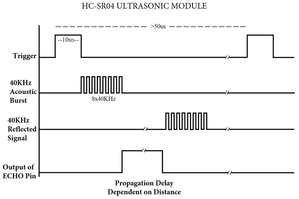
Fig : Representation of trigger signal, acoustic bursts, reflected signal and output of echo pin.
The microcontroller interprets the time signal into distance using the following functions:
Theoretically, the distance can be calculated using the TRD (time/rate/distance) measurement formula. Since the calculated distance is the distance traveled from the ultrasonic transducer to the object—and back to the transducer—it is a two-way trip. By dividing this distance by 2, you can determine the actual distance from the transducer to the object. Ultrasonic waves travel at the speed of sound (343 m/s at 20°C). The distance between the object and the sensor is half of the distance traveled by the sound wave. The following equation calculates the distance to an object placed in front of an ultrasonic sensor:
ULTRASONIC SENSOR WORKING STEPS:

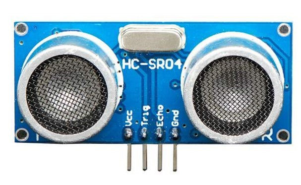
Fig: pin diagram of a ultrasonic sensor .
As shown there are four pins viz. +5V (Vcc pin), GND, Trigger pin and Echo pin.
Following are the Step by step working of ultrasonic sensor:
STEP-1: Make 'TRIGGER' pin of sensor high for some duration (say 10µs). This will initiate sensor cycle.
STEP-2: Eight pulses of 40 KHz are transmitted from transmitter part of sensor. After this is done, 'ECHO' pin goes high from low state.
STEP-3: After the transmission, transmitted signal gets reflected from the nearby object and returns back to the sensor.
STEP-4: When the ultrasonic sensor detects reflected wave, 'ECHO' pin of sensor goes low.
STEP-5: The time duration when ECHO pin is high will provide distance between sensor and detected object.
STEP-6: The ultrasonic sensor is programmed in such a way that if no object is found then ECHO pin remains high for 38ms and will go low again
Applications:
Multiple areas of engineering use ultrasonic sensors. “No-contact” distance measuring is very useful in automation, robotics, and instrumentation. Below, are some of the applications of ultrasonic sensors:
Ultrasonic Anemometers:
Weather stations commonly used anemometers since they detect wind speed and direction efficiently. The 2D anemometers can measure only the horizontal component of wind speed and direction, whereas 3D anemometers can measure the vertical component of wind, as well.
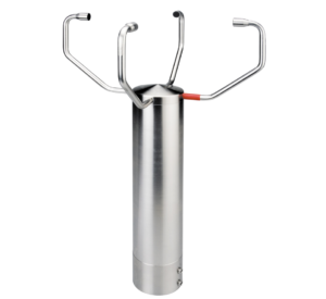
Fig: A 2D Ultrasonic anemometer detects the horizontal component of wind speed and direction
Apart from measuring wind speed and direction, ultrasonic anemometers can also measure temperature because the speed of ultrasonic sound waves is affected by variations in temperature while maintaining independence from changes in pressure. Temperature is calculated by measuring speed variations in ultrasonic sound.
The ultrasonic anemometer is more durable as compared to the cup anemometer and vane anemometer since it has no moving parts and it operates using ultrasonic sound waves.
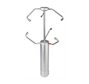
Fig: A 3D Ultrasonic anemometer measures both horizontal and vertical components of the wind speed and direction.
Tide gauge
A tide gauge is used to monitor sea level. It also detects tides, storm surges, tsunamis, swells, and other coastal processes. A tide gauge can use an ultrasonic sensor to detect real-time water level. The gauge is often linked to an online database where a record is maintained, and in case of a risky situation, the system can trigger an alarm.
Tank level
Measuring fluid level in a tank is similar to a tide gauge. However, in this case, the fluid can be clear water, a corrosive chemical, or a flammable fluid. Unlike optical sensors and float switches, ultrasonic sensors are less likely to corrode as they do not make contact with the fluid.
Functional in sunlight
The sunlight at Earth’s surface is composed of around 52-55% of infrared light. If an infrared sensor detects an object using infrared light, the process is disturbed due to the interference of infrared light present in sunlight. However, ultrasonic sensors are not affected by the infrared spectrum present in sunlight.
UAV navigation
Unmanned aerial vehicles (UAVs)—or drones—commonly use ultrasonic sensors for monitoring any objects in the UAV’s path and distance from the ground.

The autonomous feature of detecting safe distances enables the aircraft to avoid crashing. And as the flight of path changes instantaneously, the ultrasonic detection of distances can prevent a drone from crashing.
Limitations of ultrasonic sensors
Ultrasonic sensors such as the HC-SR04 can efficiently measure distances up to 400 cm with a slight tolerance of 3 mm. However, if a target object is positioned such that the ultrasonic signal is deflected away rather than reflected back to the ultrasonic sensor, the calculated distance can be incorrect. In some cases, the target object is so small that the reflected ultrasonic signal is insufficient for detection, and the distance cannot be measured correctly.
Furthermore, objects like fabric and carpet can absorb acoustic signals. If the signal is absorbed in the target object’s end, it cannot reflect back to the sensor, and hence, the distance cannot be measured.

Fig : Ultrasonic sensor measuring distance from object during drone’s flight.
The intense sensitivity of ultrasonic sensors makes them efficient, but that sensitivity can also cause problems. Ultrasonic sensors can detect false signals coming from the airwaves disturbed by an air conditioning system and a pulse coming from a ceiling fan, for instance.
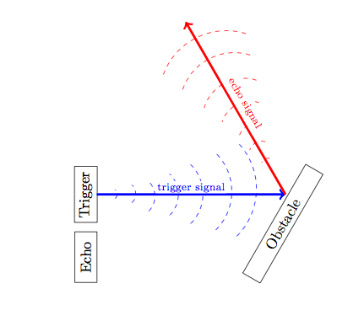
Fig : Representation of ultrasonic signal deflected due to target object’s position, resulting in error.
Ultrasonic sensors can detect objects placed within their range, but they cannot distinguish between different shapes and sizes. However, one can overcome this limitation can by using two sensors instead of just one sensor. One can install both sensors a distance away from each other, or they can be adjacent. By observing the overlapped shaded region, one can get a better idea of the shape and size of the target object.
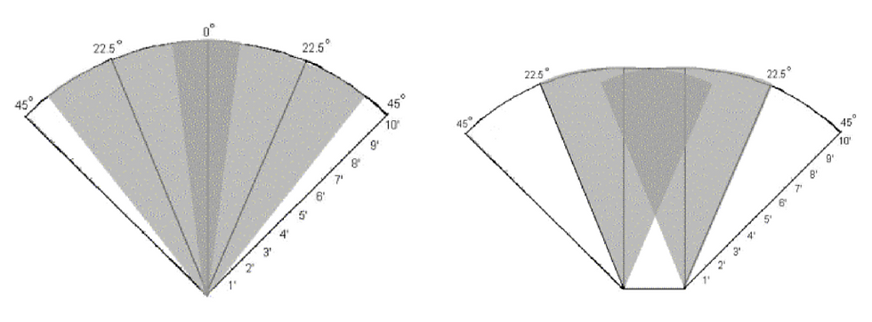
Fig: Representation of overlapping region when one places two ultrasonic sensors at a distance or adjacent to each other.
Types of Ultrasonic Sensor
There are 3 pin modules,4 pin as well as 5 pin modules ultrasonic sensors as shown below.
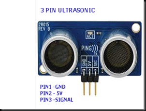
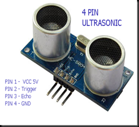

5 PIN MODULE
SPECIFICATIONS:
> The module includes ultrasonic transmitter, receiver and control circuit .
> Its stable performance and high ranging accuracy make it a popular module in Robotics.
> There are 5 pins out of the module, VCC, Trig, Echo, OUT & GND.
> The name of 4th pin “OUT “ is misguiding. As such no output is available at this pin.This is a Mode Select pin. Generally it is left unused.
> It operates at 5V DC & consumes 15mA current. Range of sensing is from 3cm up to 400cm with a resolution of 1cm.
> Trigger pulse width is 10us.
5 pin module can be used as 4 pin or 3 pin module.
o If we leave out the 4th pin (OUT) in a 5 Pin Module , it behaves as a 4 pin Module.
o If you Ground the 4th pin then it behaves as a 3 pin PING module.
Interfacing Ultrasonic Sensor

Code to Note
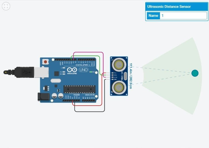
The Ultrasonic sensor has four terminals - +5V, Trigger, Echo, and GND connected as follows −
Connect the +5V pin to +5v on your Arduino board.
Connect Trigger to digital pin 7 on your Arduino board.
Connect Echo to digital pin 6 on your Arduino board.
Connect GND with GND on Arduino.
In our program, we have displayed the distance measured by the sensor in inches and cm via the serial port.
Arduino Code:
int trigPin = 10;//TRIG connected to pin 10
int echoPin = 9;//ECHO connected to pin 9
long time;
int distance;

void setup()//repeats only once

{ pinMode(10,OUTPUT);//TRIG pin set as output
 pinMode(9,INPUT); //ECHO pin set as input
 Serial.begin(9600); //begin communication
}

void loop() //repeats continuously
{
 digitalWrite(10,LOW); //TRIG pin cleared
 delayMicroseconds(2); //delay of 2micro seconds given

 digitalWrite(10,HIGH);  //TRIG pin set high i.e. signal transmitted
 delayMicroseconds(10); //delay of 10 microseconds
 digitalWrite(10,LOW);  //TRIG low again

 //calculating the distance;
 time = pulseIn(9,HIGH);//to calculate time between transmission
  //and reception of the signal
 distance = time*0.034/2; // For echo, D = vt/2
 //calculating the distance
 Serial.print("Distance: ");
 Serial.println(distance);

}
Schematic Diagram:

Result:
You will see the distance measured by sensor in inches and cm on Arduino serial monitor.
Arduino Interference With Ultrasonic Sensor ,LED’s and RGB Light
Glowing different LEDs at different proximities of the Ultrasonic sensor
SCHEMATIC:

CODE:
int inches = 0;
int cm = 0;

const int pingPin = 7;
int red=11;
int blue=10;
int green=9;

long readTime(int triggerPin, int echoPin)
{
 pinMode(triggerPin, OUTPUT);
 digitalWrite(triggerPin, LOW);// Clear the trigger
 delayMicroseconds(2);
  // Sets the trigger pin to Low state for 2 microseconds
 digitalWrite(triggerPin, HIGH);
 delayMicroseconds(10);
 digitalWrite(triggerPin, LOW);
 pinMode(echoPin, INPUT);
  // Reads the echo pin, and returns the sound wave travel time in microseconds
 return pulseIn(echoPin, HIGH);
}

void setup()
{
 Serial.begin(9600);
 pinMode(red,OUTPUT);
 pinMode(blue,OUTPUT);
 pinMode(green,OUTPUT);
}

void loop()
{
 // measure the ping time in cm
 cm = 0.01723 * readTime(7, 7);
 // convert to inches by dividing by 2.54
 inches = (cm / 2.54);
 Serial.print(inches);
 Serial.print("in, ");
 Serial.print(cm);
 Serial.println("cm");
  delay(100); // Wait for 100 millisecond(s)

 //conditions for RGB LED
 if(inches<40){
 digitalWrite(red,HIGH); //Red colour appears in the RGB LED
 digitalWrite(green,LOW);
 digitalWrite(blue,LOW);
 }
 if(inches>40 && inches<80){
 digitalWrite(red,LOW);
 digitalWrite(green,LOW);
 digitalWrite(blue,HIGH); //BLUE colour appears in the RGB LED

 }
 if(inches>80){
 digitalWrite(red,LOW);
 digitalWrite(green,HIGH); //GREEN colour appears in the RGB LED
 digitalWrite(blue,LOW);
 }
}
Result:
When we change the distance of object different different colours will appear on a single RGB LED which is capable of showing all type of colours and mixing colours.So we are able to see different colours of particular specified range.


Comments